
This is a short howto on building a simple wireless groundstation for 10-20 km UAV telemetry. For simplicity reasons the groundstation has no tracking capabilities. The user’s input device can be a laptop or a tablet/smartphone (android for now).
The input device connects via bluetooth (SPP) to the groundstation and the signal is relayed from there via RFD 900 telemetry modem (3DR modem does work as well). The RFD 900 modem has a built in diversity antenna system. It can use 2 different antennas. In my case an omni-directional rubber duck antenna for short range and a direction patch antenna for long range. The patch antenna must be pointed roughly into the direction of the UAV (45° angle).
I have used a teensy 3.0 board to do the message buffering/passing between the bluethooth modem, a USB port and the RFD900. The teensy costs roughly usd 20, has 3 hardware UARTs and packs a fair amount of power (Cortex M4 up to 96MHz).
 |
| Internals |
 |
| tripod |
Bill of Materials
Part
|
Price
|
Link
|
Teensy 3.0
|
$19.00
|
|
BlueSmirf Gold
|
$64.95
|
|
RFD 900
|
$89.50
|
|
uBEC (2-4S)
|
$ 4.03
|
|
Configure Bluetooth Modem
The BlueSmirf Gold uses the RN-41 AT command set. By default, the modem should be set to 57.6 kilo baud. This is the default speed for wireless telemetry also, this means it should work aut of the box if wired correctly to the teensy (or directly to the RFD 900 modem). More information on wiring a BlueSmirf to an FTDI cable can be found here.
Wiring
This illustration describes the wiring between teensy 3.0, BlueSmirf Gold and RFD-900.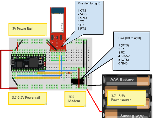
Blue: Teensy TX <-> Modem RX
Yellow: Teensy RX <-> Modem RX
Teensy 3.0 Pins

Code
The programm that is running on the teensy can do 2 things:
just play relay between serial links (passthrough). This is low latency but does not allow modifying packages.
buffered. In this mode the serial link will buffer until it receives a full mavlink message. Before sending it to the target, it can be modified or dropped (or routed/duplicated to another serial port).
The code relies on the AP_HAL and a modified GCS_Mavlink library (without FastSerial, we have hardware UARTs and mavlink 0.9 removed).
ArduMavProxy.ino
#include <GCS_MAVlink.h>
#include "ArduMavProxy.h"
// #define DBG
// message structs
static mavlink_message_t msg1;
static mavlink_message_t msg2;
static mavlink_message_t msg3;
static mavlink_status_t status1;
static mavlink_status_t status2;
static mavlink_status_t status3;
// Serial devices
static comm_t s_src = {"", 0, &Serial1, msg1, status1, 0, 1};
static comm_t s_modem = {"", 0, &Serial2, msg2, status2, 0, 2};
static comm_t s_ext = {"", 0, &Serial, msg3, status3, 0, 3};
void setup() {
Serial.begin(TELEMETRY_SPEED);
Serial1.begin(TELEMETRY_SPEED);
Serial2.begin(TELEMETRY_SPEED); // FIXME: s_modem.serial->begin() doesn't work
//Serial3.begin(TELEMETRY_SPEED);
// set pins to default state
pinMode(PIN_ARM, OUTPUT);
pinMode(PIN_AUTO, OUTPUT);
digitalWrite(PIN_ARM, LOW);
digitalWrite(PIN_AUTO, LOW);
}void loop() {
// No passthrough to modem so we queue src packages
uint8_t ret1 = read_packet(&s_src, &s_modem, false);
// TODO: check for comm_t.has_packet
if (ret1) { // we got a complete message from the source
route_packet(&s_src, &s_modem);
flush_packet(&s_src);
#ifdef DBG
Serial.print("Sats: ");
Serial.print(gps_satellites_visible);
Serial.print(", fix: ");
Serial.print(gps_fix_type);
Serial.print("\t");
Serial.print(motor_armed, HEX);
Serial.print("\t");
Serial.println(base_mode, BIN);
#endif
digitalWrite(PIN_ARM, (motor_armed) ? HIGH : LOW);
digitalWrite(PIN_AUTO, (mode_auto) ? HIGH : LOW);
}
// read mavlink package from modem
uint8_t ret2 = read_packet(&s_modem, &s_src, true);
if (ret2) { // we got a complete message from the source
// TODO: implement fast passthrough for 2 channels
route_packet(&s_modem, &s_ext);
flush_packet(&s_modem);
}
#ifndef DBG
// No passthrough to modem so we queue src packages
uint8_t ret3 = read_packet(&s_ext, &s_modem, false);
if (ret2) { // we got a complete message from the source
route_packet(&s_ext, &s_modem);
flush_packet(&s_ext);
}
#endif
}
ArduMavProxy.h
// Get the common arduino functions
#if defined(ARDUINO) && ARDUINO >= 100
#include "Arduino.h"
#else
#include "wiring.h"
#endif
#define TELEMETRY_SPEED 57600 // How fast our MAVLink telemetry is coming to Serial
#define PIN_ARM 13
#define PIN_AUTO 14
#define MAVLINK_FRAME_LENGTH 263
#include <GCS_MAVlink.h>
#include "include/mavlink/v1.0/mavlink_types.h"
static uint8_t base_mode=0;
static bool motor_armed = 0;
static uint8_t mode_auto = 0;
typedef struct comm_t {
char buffer[MAVLINK_FRAME_LENGTH + 1];
int buffer_count;
Stream *serial;
mavlink_message_t msg;
mavlink_status_t status;
bool has_message;
uint8_t chan;
};
util.ino
// utility methods
// bit juggling
boolean getBit(byte Reg, byte whichBit) {
boolean State;
State = Reg & (1 << whichBit);
return State;
}
byte setBit(byte &Reg, byte whichBit, boolean stat) {
if (stat)
Reg = Reg | (1 << whichBit);
else
Reg = Reg & ~(1 << whichBit);
return Reg;
}
/**
* flush input buffer
*
* the user must make sure that the buffered packet was used before flusing.
*/
void flush_packet(comm_t *src) {
src->buffer_count = 0;
src->buffer[0] = '\0';
}
/**
* write buffer to serial
*
* writes a buffer and decoded incoming mavlink serial packet to another
* serial port.
*/
void route_packet(comm_t *src, comm_t *target) {
for (int i=0; i <= src->buffer_count; i++)
target->serial->write(src->buffer[i]);
//flush_packet(src);
}
/**
* read a mavlink packet
*
* returns 1 if we got a complete packet. returns 0 if we need to read
* more into the stream.
*
* passthrough is for minimal latency. Best used for sniffing or routing only.
*/
uint8_t read_packet(comm_t *src, comm_t *target, bool passthrough) {
//grabing data
while(src->serial->available() > 0) {
// the packet should have been used, flush it to prevent buffer overflows
if (src->has_message) {
src->has_message = false;
flush_packet(src);
}
char c = src->serial->read();
// buffer the received character
src->buffer[src->buffer_count] = c;
(src->buffer_count)++;
// buffer overflow protection
if (src->buffer_count == MAVLINK_FRAME_LENGTH) {
// flush stream buffer if full
//src->buffer_count = 0;
//src->buffer[0] = '\0';
flush_packet(src);
}
if (passthrough)
target->serial->write(c);
// try to grab message, decode if complete
if(mavlink_parse_char(MAVLINK_COMM_0, c, &(src->msg), &(src->status))) {
src->has_message = true;
return 1;
}
}
return 0;
}
Download
Connecting
Windows Mission Planner
You have to options: connect with USB-A to Micro-USB B cable to teensy or use bluetooth. The following section describes the Bluetooth connectivity setup.
Enable Bluetooth and pair with the ground station.
 |
| Add bluetooth adapter from task tray |
 |
| Your device should show up here |
 |
| Make sure you get the manual pairing option. |
 |
| Enter PIN
|
 |
| Device Paired |
 |
Verify from devices. Right click the device and select Properties » Services (“SPP” should be displayed).
|
If done, the comm port shown in the last screenshot can be used from MP to connect (57.6K).
DroidPlanner (Android)
Enable Bluetooth and pair with the ground station.
Open DroidPlanner, select settings and configure the modem to BLUETOOTH.
Andropilot (Android)
Enable Bluetooth and pair with the ground station.
After launching the program, click on the [Bluetooth] overlay button to connect.


