Everything is now much tighter packed! I decided to use RJ45 to connect every six-pack of rockets (spare 2 pins used as 12V power supply). The arduino's FTDI port can be easily used with an FTDI breakout board.
Lession learned:
Use small pads only where needed (in tight spots)
Pull out all available ɥC pins
plan mount holes
put as much as possible onto the lower layer (easier to solder)
8705 is a very useful power regulator when used with 3-5 cell LIPOs
Hardware documentation is available as PDF or you can get the whole source code including pcb (beta version).
Yay, today I made the first prototype PCB. Already soldered the absolute minimum onto it for tesing.
Top layer, with Arduino Pro mini 5V (top) and a single 8 bit shift register (below the Arduino).
Bottom layer.
The final layout will certainly differ from this a bit. I did not know how painful it is to solder headers which have connections on the front layer. Thanks to swiss machine pins it is possible without funny chemicals.
Also, the copper around the via and pin holes are much too small. They make drilling and sometimes proper soldering very hard. It's just looks ugly too.
Further more, a new design decision was to use RJ45 as connector for the expansion to the electric fuses (connectors at the bottom).
Not much time left until it is Silvester. The remote controlled fireworks launcher is in prototyping stage. I got the first PCB layout together.
The pcb files are created with an open source program called pcb (free as in free code and free of charge) which should compile on nearly all UNIX like operating systems (incuding, osx, cygwin or mingw for windows).
The pcb application is also able to generate gerber files which are included in the pcb files download.
Some alpha code (written in C) is available to be run on an Arduino Pro Min 5V.
As a follow up to the first tests with the 74HC594 and 74HC595 with Arduino I got some more 595 delivered, finally chaining them together. This example uses the 74HC595 chip.
First, you need to install (extract) the MM74HC595 library I wrote into your "<\libraries>" folder.
/** * Board: Pro Mini 5V * * Chained 74HC595 8 bit shift register demo. Knight Rider! * * $Id: test_74HC595.pde 319 2011-10-13 20:48:10Z wunderlins $ */// how many shift registers are we using in serie? (must be >=1)
#define NUM_SHIFT_REGISTERS 3
// include library (must be installed unter <sketches>/libraries/MM74HC595/)// http://spliffy.freeshell.net/hardware/MM74HC595.zip
#include <MM74HC595.h>/** * Arduino pins: * * PIN_SER: is the arduino serial pin * PIN_SCK: is the arduino pin for the shift register * PIN_RCK: is the arduino pin for the output register */int PIN_SER = 8; // pin 14 on the 75HC595int PIN_SCK = 9; // pin 12 on the 75HC595int PIN_RCK = 10; // pin 11 on the 75HC595int i = 0;
intdirection = 1; // 1 = L2R, -1 R2L// shift register instance
MM74HC595 registers(PIN_SER, PIN_SCK, PIN_RCK, NUM_SHIFT_REGISTERS);
// module pins already initialzedvoidsetup() {;}
voidloop(){
// reset all pins (set to LOW)
registers.reset();
// set pin(s) to high
registers.set(i, true);
// activate outputs
registers.update();
// check if we have to change directionif (i+1 == NUM_SHIFT_REGISTERS * 8) {
direction = -1;
} elseif (i == 0) {
direction = 1;
}
i += direction;
delay(100);
}
As a follow up to the bit shift register (74HC595) example I ordered some more of these. Unfortunately MM74HC594 (Datasheet) were delivered. These chips are a bit more complicated to handle. Here is the same example as in the previous post:
/** * Board: Pro Mini 5V * * Chained 74HC595 8 bit shift register demo. Knight Rider! * * Based on: http://bildr.org/2011/02/74hc595/ * * $Id: test_74HC595.pde 309 2011-10-13 18:50:44Z wunderlins $ */int PIN_SER = 8; //pin 14 on the 75HC595int PIN_SCK = 9; //pin 12 on the 75HC595int PIN_RCK = 10; //pin 11 on the 75HC595// how many shift registers are chained? (must be >=1)
#define NUM_SHIFT_REGISTERS 3
// store all LED states in this array. every element of the array stores a // binary mask of of 8 pin states (per chip).
uint8_t pins[NUM_SHIFT_REGISTERS];
// reset all chips to 0void sr_reset() {
for(int i=0; i<NUM_SHIFT_REGISTERS; i++)
pins[i] = 0;
}
// set a pin high or low. if you have 1 chip use pins 0-7, if youhave 2 chips// you might use 0-7, 8-15 as pin numbers. state sets LED on (true) or // off (false)void sr_set(int pin, bool state) {
// check which register to manipulateint current = pin / 8;
int p = pin - current*8;
if (state == true) // set pin to true
pins[current] |= 1 << p;
else { // set pin to falseint tmp = ~pins[current];
tmp |= 1 << p;
pins[current] = ~tmp;
}
}
// check if pin is set to highboolean sr_isset(int pin) {
int current = pin / 8;
int p = pin - current*8;
if ((1 << p) & pins[current])
returntrue;
returnfalse;
}
// move data into shift register and from there into storage at once. make // sure to fill the shift pins before acitivating the storage pins.void sr_update() {
digitalWrite(PIN_SCK, LOW);
// set statefor(int i=8 * NUM_SHIFT_REGISTERS - 1; i >= 0 ; i--) {
digitalWrite(PIN_RCK, LOW);
if (sr_isset(i))
digitalWrite(PIN_SER, HIGH); // ONelsedigitalWrite(PIN_SER, LOW); // OFFdigitalWrite(PIN_RCK, HIGH);
}
digitalWrite(PIN_SCK, HIGH);
}
voidsetup(){
pinMode(PIN_SER, OUTPUT);
pinMode(PIN_SCK, OUTPUT);
pinMode(PIN_RCK, OUTPUT);
// initialize pin state
sr_reset();
}
int i = 0;
intdirection = 1; // 1 = L2R, -1 R2Lvoidloop(){
sr_reset();
sr_set(i, true);
sr_update();
if (i+1 == NUM_SHIFT_REGISTERS * 8) {
direction = -1;
} elseif (i == 0) {
direction = 1;
}
i += direction;
delay(100);
}
/** * Board: Pro Mini 5V * * $Id: test_74HC595.pde 293 2011-10-06 17:30:05Z wunderlins $ */int SER_Pin = 8; //pin 15 on the 75HC595int RCLK_Pin = 9; //pin 12 on the 75HC595int SRCLK_Pin = 10; //pin 10 on the 75HC595//How many of the shift registers - change this
#define number_of_74hc595s 1
#define numOfRegisterPins number_of_74hc595s * 8
boolean registers[numOfRegisterPins];
voidsetup(){
pinMode(SER_Pin, OUTPUT);
pinMode(RCLK_Pin, OUTPUT);
pinMode(SRCLK_Pin, OUTPUT);
//reset all register pins
clearRegisters();
writeRegisters();
}
//set all register pins to LOWvoid clearRegisters() {
for(int i = numOfRegisterPins - 1; i >= 0; i--){
registers[i] = LOW;
}
}
//Set and display registers//Only call AFTER all values are set how you would like (slow otherwise)intdirection = 1; // 1 = L2R, -1 R2Lvoid writeRegisters(){
digitalWrite(RCLK_Pin, LOW);
for(int i = numOfRegisterPins - 1; i >= 0; i--){
digitalWrite(SRCLK_Pin, LOW);
int val = registers[i];
digitalWrite(SER_Pin, val);
digitalWrite(SRCLK_Pin, HIGH);
}
digitalWrite(RCLK_Pin, HIGH);
}
//set an individual pin HIGH or LOWvoid setRegisterPin(int index, int value){
registers[index] = value;
}
int i = 0;
voidloop(){
clearRegisters();
setRegisterPin(i, HIGH);
writeRegisters(); //MUST BE CALLED TO DISPLAY CHANGES//Only call once after the values are set how you need.if (i+1 == numOfRegisterPins) {
direction = -1;
} elseif (i == 0) {
direction = 1;
}
i += direction;
delay(100);
}
The maple IDE is only offered as 32Bit java binary/bytecode. On a 64Bit linux with a default java installation maple-ide will refuse to start with the following error:
$ ./maple-ide
java.lang.UnsatisfiedLinkError: /mnt/aaa/bin/maple-ide-v0.0.12/lib/librxtxSerial.so: /mnt/aaa/bin/maple-ide-v0.0.12/lib/librxtxSerial.so: wrong ELF class: ELFCLASS32 (Possible cause: architecture word width mismatch) thrown while loading gnu.io.RXTXCommDriver
Exception in thread "main" java.lang.UnsatisfiedLinkError: /mnt/aaa/bin/maple-ide-v0.0.12/lib/librxtxSerial.so: /mnt/aaa/bin/maple-ide-v0.0.12/lib/librxtxSerial.so: wrong ELF class: ELFCLASS32 (Possible cause: architecture word width mismatch)
    at java.lang.ClassLoader$NativeLibrary.load(Native Method)
    at java.lang.ClassLoader.loadLibrary0(ClassLoader.java:1807)
    at java.lang.ClassLoader.loadLibrary(ClassLoader.java:1732)
    at java.lang.Runtime.loadLibrary0(Runtime.java:823)
    at java.lang.System.loadLibrary(System.java:1028)
    at gnu.io.CommPortIdentifier.(CommPortIdentifier.java:123)
    at processing.app.Editor.populateSerialMenu(Editor.java:795)
    at processing.app.Editor.buildToolsMenu(Editor.java:612)
    at processing.app.Editor.buildMenuBar(Editor.java:413)
    at processing.app.Editor.(Editor.java:187)
    at processing.app.Base.handleOpen(Base.java:608)
    at processing.app.Base.handleOpen(Base.java:573)
    at processing.app.Base.handleNew(Base.java:475)
    at processing.app.Base.(Base.java:245)
    at processing.app.Base.main(Base.java:149)
You will be able to select a folder for your sketches and then the application will crash.
The problem can be solved by installing the 32Bit version of Java (i chose the sun/oracle one):
$ sudo apt-get install ia32-sun-java6-bin
Then modify the startup script maple-ide to point to the appropriate java installation. Adjust JAVA_HOME and the PATH environment variables:
#!/bin/sh
APPDIR="$(dirname -- "${0}")"

cd $APPDIR

# /usr/lib/jvm/ia32-java-6-sun/jre/bin/
export JAVA_HOME=/usr/lib/jvm/ia32-java-6-sun/jre
export PATH=$JAVA_HOME/bin:$PATH

for LIB in \
    java/lib/rt.jar \
    java/lib/tools.jar \
    lib/*.jar \
    ;
do
    CLASSPATH="${CLASSPATH}:${APPDIR}/${LIB}"
done
export CLASSPATH

LD_LIBRARY_PATH=`pwd`/lib:${LD_LIBRARY_PATH}
export LD_LIBRARY_PATH

export PATH="${APPDIR}/java/bin:${PATH}"

java -Dswing.defaultlaf=com.sun.java.swing.plaf.gtk.GTKLookAndFeel processing.app.Base
ArduPilotMega (APM) is a very capable Auto Pilot solution based on an ATmel2650 micro controller and a powerful and complete software solution for fixed wing, helicopter and multi-copter aircrafts. Various sensor solutions are available and supported (gyro, accelerometer, barometric altimeter, pitot speed, gps, range sensors, telemetry comm, magnetometer, etc.).
qGroundControl lets you control your UAV/drone from software over various communication methods (wifi, bluetooth, GSM, USB, etc.). Communication between UAV and ground control software is achieved with the MAVLink protocol.
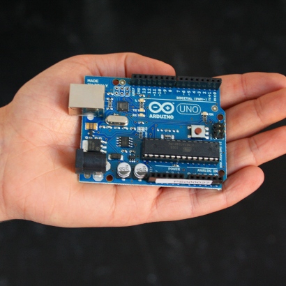
Need a simple/small/cheap microprocessor with loads of peripherals (I2C) that is easy to tinker with? Arduino's products might be something for you. The Arduino Uno sports a atmega328 (Atmel 8-bit AVR RISC-based microcontroller) with 1K EEPROM, 2K SRAM and 32 KB Flash Memory.
Many devices can be connected trough I2C. Devices such as 3D gyros, temperature-, humidity-, brightness sensors, external storage as well as a gps receivers.
xxdiff is an X11 application for displaying differences of two files.
Installation on Debian: $ sudo apt-get install xxdiff-scripts
Example usage with subversion (if you run the above command and are on X11 with xxdiff installed and in your $PATH, xxdiff should start, else console output should appear):
#!/usr/bin/env bash
# $Id: svndiff_gui.sh 174 2011-05-05 19:13:55Z wus $

# use xxdiff when available and on X11

if [[ -n "$DISPLAY" && -x `which xxdiff` ]]; then
 svn stat
 read -p "Graphical diff? [Y/n]: " proceed
 if [[ "$proceed" == "" || "$proceed" == "y" || "$proceed" == "Y" ]]; then
  xx-svn-diff $@
  exit $?
 fi
fi

svn diff $@
tar zxvf Plone-YOURVERSION-UnifiedInstaller.tgz
cd Plone-YOURVERSION-UnifiedInstaller
./install.sh standalone
w3m /usr/local/Plone/zinstance/README.html
less /usr/local/Plone/zinstance/buildout.cfg
Find start script at:
/usr/local/Plone/zinstance/bin/plonectl
Change Admin password:
http://localhost:8080/manage (check zinstance/buildout.cfg for port)
Enter the ZMI root
Change the password for the admin user in the acl_users folder in the root
Log in with the new password
Run plone 4 from init.d on Debian:
For this, you need to copy the init script from below to /etc/init.d/plone and make it executable (chmod 755), then run update-rc.d
# update-rc.d plone defaults
Debian init script:
#! /bin/sh -e
# /etc/init.d/plone
### BEGIN INIT INFO
# Provides:          plone
# Required-Start:    $syslog $time $remote_fs
# Required-Stop:     $syslog $time $remote_fs
# Default-Start:     2 3 4 5
# Default-Stop:      0 1 6
# Short-Description: Plone 4
# Description:       Plone 4 instance installed with the unified installer.
### END INIT INFO
#
# Author: Simon Wunderlin, swunderlin () gmail , com
#
set -e

ZINSTANCE=/usr/local/Plone/zinstance

PATH=/bin:/usr/bin:/sbin:/usr/sbin:$ZINSTANCE/bin
DAEMON=$ZINSTANCE/bin/plonectl

test -x $DAEMON || exit 0

. /lib/lsb/init-functions

case "$1" in
    start)
 log_daemon_msg "Starting plone"
 $DAEMON start >> /var/log/plone.log
 log_end_msg $?
    ;;
  stop)
 log_daemon_msg "Stopping plone"
 $DAEMON stop >> /var/log/plone.log
 log_end_msg $?
    ;;
  force-reload|restart)
    $DAEMON stop
    $DAEMON start
    ;;
  *)
    echo "Usage: /etc/init.d/plone {start|stop|restart|force-reload}"
    exit 1
    ;;
esac

exit 0
Automating tasks is what I do now and then and keep forgetting. This is the reason I keep a log of interesting information (interesting to me). My primary platform is Debian, most things here will work out of the box on Debian.